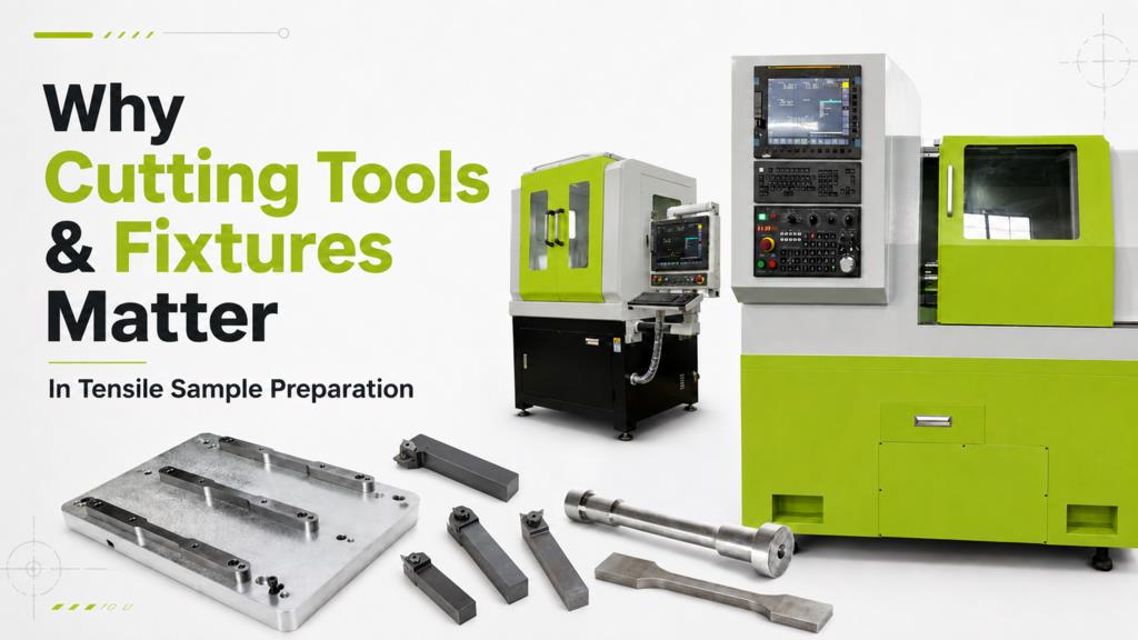
A tensile test starts before the specimen reaches the test frame. Reported strength, elongation, and failure location depend on the material and on how the specimen was cut, held, finished, and inspected.
Cutting tools and fixtures affect gauge width, edge quality, shoulder transitions, burr formation, heat, and surface finish. A worn cutter can leave a rough edge. A loose fixture can let the blank move during machining. A damaged collet or holder can add runout that shows up as dimensional scatter.
For labs preparing flat or round tensile samples, these details are part of process control. Many teams track tensile sample preparation consumables such as carbide end mills, inserts, collets, holders, coolant, and clamping components because small changes in tooling can show up in the finished specimen.
The test machine measures how the specimen behaves under load. If the specimen already carries burrs, heat marks, chatter, or alignment errors, the result may include machining effects that do not belong to the material itself.
Tool Wear Can Change The Specimen Before Testing Begins
Tool wear usually appears gradually. In most labs, the problem appears gradually. A cutter that produced clean gauge edges at the start of the week may begin leaving burrs, rougher edges, or slightly different dimensions after repeated use. The change can be easy to miss if the lab only checks the final tensile result.
Tool wear matters because tensile specimens are sensitive to geometry and surface condition. The reduced section, shoulder radius, and transition into the grip area are designed to create a controlled failure location. A dull edge, chatter mark, burr, or heat-affected surface can change how stress is distributed through the sample.
Tool wear also depends on the material being machined. Aluminum may cut easily but can build up on the edge. Stainless steels and hard alloys can increase cutting forces and heat. Plastics can smear or melt if the tool, speed, or chip evacuation is wrong. Composites can create abrasive wear and edge fraying.
A worn tool can also increase downstream manual work. More deburring may be needed. More parts may need dimensional checks. Operators may start compensating by hand, which adds another source of variation. In a tensile sample preparation workflow, the practical control point is to identify tool wear before it becomes specimen drift.
Signs A Cutter Is No Longer Producing Clean Specimens
Labs can often see tool wear before it becomes a major testing problem. The signs often appear in the machined edge, the sound of the cut, or the number of parts needing rework.
Common warning signs include:
- Burrs appearing more often on the gauge edge
- Surface finish becoming dull, torn, or uneven
- Measured gauge width starting to drift
- Spindle load or cutting noise increasing
- Parts needing more hand deburring than usual
- Edge wear becoming visible during inspection
- Test failures moving toward the shoulder or grip transition
None of these signs automatically invalidates a specimen. They should prompt the lab to check the cutter, tool record, fixture condition, and recent inspection data. If several signs appear together, the preparation process may be moving away from its normal range.
Good tool records make that review easier. A lab can track cutter use by material type, part count, visible edge condition, finish quality, and rework frequency. When tensile results begin to scatter, those records can show whether preparation changed before the material did.
Fixtures Hold The Gauge Geometry In Place
A clean cutter cannot produce a repeatable specimen if the blank is not held correctly. Fixtures control where the material sits, how it is supported, and whether it moves during machining. For flat tensile specimens, that affects gauge width, shoulder radius, grip area, and edge symmetry.
Poor clamping can create several problems. If the blank shifts during cutting, the reduced section may become asymmetric. If the blank is not fully supported, the cutter can create chatter or taper. If debris sits under the material, the part may sit at a slight angle. If a soft or thin blank is over-clamped, the fixture can mark or deform it before cutting begins.
This is why flat specimen preparation depends on the whole setup, not only the CNC program. The toolpath may be correct, but the final part still depends on fixture cleanliness, clamping pressure, blank seating, collet condition, holder runout, and tool engagement. In high-throughput labs, flat tensile specimen preparation machines rely on stable fixturing so repeated specimens stay within the expected geometry range.
Clamping also affects repeatability between operators. One operator may clean the fixture surface every cycle. Another may miss chips near the support area. One may tighten clamps evenly. Another may load a thin blank with uneven pressure. These differences can create small geometry changes that are hard to see until the lab measures the specimens.
Clamping Problems That Show Up In The Finished Specimen
Fixture issues often appear as physical signs on the machined part. Chatter marks can point to movement during cutting. Uneven edges may suggest the blank shifted or lifted. Taper can indicate poor support, incorrect seating, or a fixture surface that needs cleaning. Marks in the grip area may come from excessive clamp force or damaged contact surfaces.
Thin materials need particular care. Too little clamping force allows movement. Too much can deform the blank. Soft metals, plastics, and some composites can also show clamp marks that later affect handling or gripping in the tensile test.
A fixture does not need to be replaced often if it is maintained properly, but it does need routine attention. Chips, coolant residue, worn contact points, loose fasteners, and damaged clamps can all change how the blank sits. For specimen machining, fixture maintenance is part of keeping the geometry repeatable from one sample to the next.
Small Dimensional Changes Can Move The Failure Point
Tensile specimens are designed to fail in the reduced section, not at the shoulder, grip transition, or machined edge. That design only works when the gauge geometry is controlled. Width, thickness, radius, straightness, surface finish, and edge condition all affect how load moves through the specimen.
Even small dimensional changes can move the fracture location. A narrow spot in the gauge section can concentrate stress. An uneven shoulder radius can pull stress away from the intended failure area. A burr can act like a small notch. A scratch near the reduced section can become the starting point for fracture. If the specimen breaks outside the expected region, the lab may need to question the preparation process before accepting the result.
This is especially important for flat tensile specimens. The reduced section depends on clean transitions between the gauge area and shoulders. If the cutter leaves asymmetry, chatter, or rough edges, the specimen may not represent the material cleanly. A test frame can measure force and elongation accurately, but it cannot separate material behavior from machining damage after the specimen has already been prepared.
ASTM E8/E8M and ISO 6892-1 are common reference points for metallic tensile testing. For labs working under NADCAP or moving toward NADCAP-related quality expectations, the same preparation discipline becomes even more important. Strong tolerances, dimensional accuracy, repeatable gauge geometry, and controlled surface finish help show that the specimen preparation process is stable, traceable, and capable of supporting stricter audit and testing requirements.
The details vary by specimen type and lab procedure, but the practical concern is consistent: the reduced section must be prepared without adding damage that changes the mechanical response. Machining, clamping, deburring, or handling should not deform the area being tested.
What Labs Should Check After Machining
Post-machining inspection does not need to be complicated, but it should be consistent. The same checks should be applied across batches, operators, materials, and machine setups.
Common checks include:
- Gauge width or diameter
- Thickness for flat specimens
- Shoulder radius and transition shape
- Burrs along the gauge edge
- Surface scratches, chatter marks, or heat marks
- Symmetry on both sides of the reduced section
- Specimen flatness and straightness
- Tool, fixture, program, and material records
When stricter surface-finish expectations apply, machining may also be followed by a controlled finishing step. A longitudinal polisher and grinder can help improve surface finish quality along the specimen length, reduce visible machining marks, and support more consistent preparation across repeated samples. This is especially useful when labs need a cleaner finish to meet tighter internal, customer, or NADCAP-related requirements.
These checks help the lab separate a material issue from a preparation issue. If a specimen breaks near the shoulder, shows unusual scatter, or produces a result outside the expected range, the preparation record gives the first place to look.
Inspection also helps reduce unnecessary retesting. If the lab can identify a burr, taper, or setup problem before the specimen reaches the tensile frame, the part can be rejected before test time is spent on unreliable data. That is especially useful in high-volume labs where specimen preparation and mechanical testing run on tight schedules.
Consumable Control Helps Labs Find Preparation Drift
Consumables are often treated as purchasing items, but they are part of specimen preparation control. A cutter, collet, insert, holder, coolant, or clamp can change the finished sample before a failed tensile test appears.
The same CNC program can produce different specimens if the cutting edge, blank support, clamping surface, or tool holding condition changes. A carbide end mill near the end of its useful life may leave more burrs. A worn collet may add runout. A dirty fixture surface may keep the blank from seating flat. A coolant change may affect heat, chip evacuation, or surface finish.
Tracking consumables gives the lab a practical way to identify drift. If gauge width begins to move out of range, the team can check cutter age, tool offsets, collet condition, fixture cleaning records, and recent material changes. If more specimens need hand deburring, the cause may be tool wear, cutting parameters, chip control, or material condition.
Different materials may need different tool-life expectations. A cutter used on aluminum may last longer than one used on stainless steel or abrasive composites. Plastics may require a different approach to avoid heat buildup or smeared edges. Harder alloys may need closer attention to tool wear, spindle load, and finish quality.
Consumable control also helps with repeatability between shifts. When operators replace tools at different points, use different deburring habits, or clean fixtures inconsistently, specimen preparation can vary even when the machine program stays the same. Tool records, inspection notes, and routine fixture checks make those differences easier to find.
For labs preparing tensile specimens every day, the practical question is whether the tool can still produce samples that meet dimensional and surface requirements.
Cleaner Preparation Makes Tensile Results Easier To Review
Preparation tools do not replace ASTM E8, ISO 6892, NADCAP-related quality systems, or internal inspection procedures. They support those procedures by keeping the specimen closer to the intended geometry before testing begins. In practice, tight tolerances, dimensional accuracy, repeatable preparation, and controlled surface finish can all help a lab move closer to stricter testing, customer, and audit requirements.
When cutters, fixtures, collets, holders, and inspection records are controlled, the lab has a cleaner path from raw blank to test-ready specimen. If tensile results begin to scatter, the team can review preparation variables before assuming the material changed.
That review can include cutter age, burr formation, fixture condition, gauge dimensions, surface marks, and failure location. If those records are consistent, the tensile result is easier to interpret. If they show drift, the lab has evidence that machining may be part of the problem.
Tensile testing depends on the specimen as much as the test frame. Clean cutting, stable fixturing, and routine inspection reduce the chance that preparation variation becomes part of the reported mechanical data.
FAQs
- Why Do Cutting Tools Matter In Tensile Sample Preparation?
Cutting tools affect gauge width, edge quality, burr formation, heat, and surface finish. A worn cutter can leave rough edges or dimensional drift that may affect where the specimen fails during tensile testing.
- How Can Fixtures Affect Tensile Specimen Quality?
Fixtures control how the blank is held during machining. Poor clamping can cause chatter, taper, shifted geometry, clamp marks, or uneven edges. These issues can make the specimen less representative of the material.
- What Are Common Signs Of Tool Wear During Specimen Machining?
Common signs include more burrs, dull or torn surface finish, drifting gauge width, higher spindle load, louder cutting noise, visible edge wear, and more hand deburring than usual.
- What Should Labs Check After Machining Tensile Specimens?
Labs should check gauge width or diameter, thickness, shoulder radius, burrs, surface scratches, heat marks, symmetry, flatness, straightness, and records for the tool, fixture, program, and material used.
- Why Can Small Dimensional Changes Affect Tensile Test Results?
Tensile specimens are designed to fail in the reduced section. Burrs, scratches, uneven shoulders, taper, or width changes can shift stress and move the fracture point away from the intended area.